 i,j efficiently with a run-length
encoding per partition which we present next:
i,j efficiently with a run-length
encoding per partition which we present next:With partitions generated by the SFC intervals, we present communication patterns by generating and synchronizing data shared interfaces of partitions with a replicated data scheme. First of all, a replicated data scheme requires independent communication buffers. To account for these replicated data scheme, we use additional stack-based communication buffers for each partition. We continue with a static number of partitions and refer to Section 5.5 for dynamic partition generation.
For our Sierpiński stack- and stream-based traversals, we first describe the replicated data layout in an abstract way. It can be implemented with a forward- and backward-traversal in the following way:
By executing an SFC-based grid traversal, communication data is written to the corresponding edge- or vertex-communication stacks. Since those output buffers are replicated, this access is race condition free. Now, the output stacks are filled with communication data of dPi.
A parallelization with a replicated data scheme allows the forward traversals being executed on all partitions in parallel and also in arbitrary order. The same holds for the synchronization operation and backward traversals. Therefore, the only required access-synchronizations are between the forward, reduce and backward traversals. So far, this is a similar approach which was also taken in [Vig12].
We next discuss important properties by using the Sierpiński SFC with a stack- and stream-based communication.
Lemma: 5.2.1 (Order of replicated data) After the first traversal, the elements on the communication stack are ordered with their creating SFC cell indices.
With communication data ordered with the SFC cell indices, this also leads to additional and for our development mandatory properties regarding the cardinality and uniqueness of data exchange:
Theorem 5.2.2 (Unique adjacent partition) All communication data for an adjacent partition Pk are consecutively stored on the communication stack. This induces an unique adjacency of partitions.
So far, we assume the knowledge on which blocks of data stored on the communication stacks are associated to which partition to be already given. We refer to this knowledge as communication meta information.
We can store this information per partition and not per cell due to two properties given by the SFC stack-based communication:
i,j efficiently with a run-length
encoding per partition which we present next:We continue with a description of the meta information for communication and how it is managed. Searching for adjacency data for each communication element can be time-consuming if iterating over all adjacency information stored for all shared hyperfaces or stored per cell. For node-based communication with each node adjacent to up to 8 cells, managing adjacency information can be also very memory demanding.
We present a solution based on both previously derived theorems:
This allows introduction of a run-length-encoded (RLE) representation of the adjacency information.
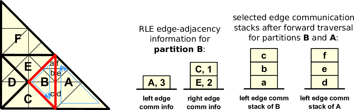
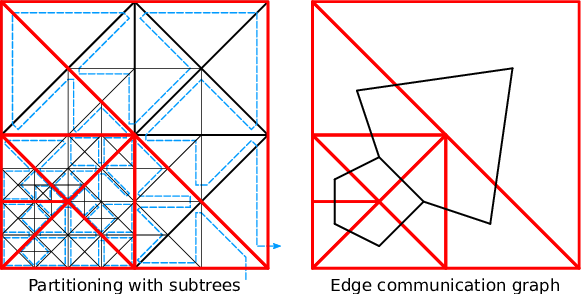
We first consider one-dimensional shared interfaces (edges) only and the information on communication edges for adjacent partitions A, B and C, respectively, given by 2, 4 and 3 shared edges. Without RLE, we can store the meta information with the tuple (A,A,B,B,B,B,C,C,C). Using our RLE, we represent m entries for edge communication referring to the same adjacent partition P with the tuple R := (P,m). We can compresses this with an RLE scheme to ((A,2),(B,4),(C,3)). Figure 5.4 gives an example of such an RLE edge communication for a single partition and Figure 5.5 shows the underlying representation of the sparse edge communication graph.
For the zero-dimensional hyperfaces (nodes), we can extend the RLE representations for the edges directly accounting for nodes: We first require that no zero-length encoded communication information for edges may be stored. This allows us to use RLE elements with m = 0 to describe a vertex shared with an adjacent partition which was not considered by the edge-based communication so far.
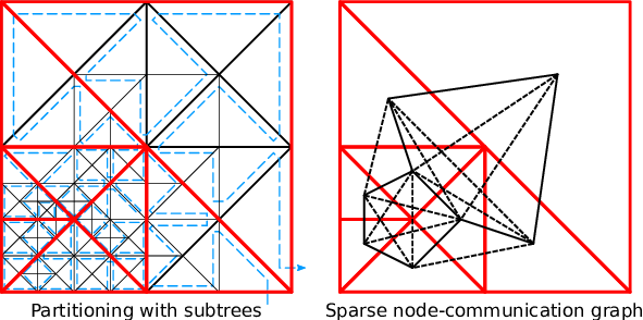
To give an example, we assume adjacent partitions A, B and C, sharing hyperfaces setup with 2 edges, 1 vertex and 3 shared edges, respectively. Storing the information on edges and vertices separately would result in edge encodings (A,A,C,C,C) for the edge communication information and (A,A,A,B,C,C,C,C) for the vertex communication information. Unifying both representations with tuples and additional markers e and v representing edges and vertices yields ((A,e),(A,e),(B,v),(C,e),(C,e),(C,e)). Here, we assume that two consecutive and identical entries also account for a vertex. Using our RLE scheme, this meta information can be further compressed to ((A,2),(B,0),(C,3)). The underlying sparse communication graph is given in Fig. 5.6. This RLE meta information is stored separately for the left and right communication buffers.
We summarize the main benetifs of using such an RLE compared to meta information stored for each shared hyperface:
By considering the communication of cell ids, the SFC traversal at the adjacent partition generates the data on the communication stacks in reversed, descending, order. This leads to the requirement of reversing the order of elements transferred block-wise.
So far, we ignored the vertices at the cell touched at first and last during traversal of a partition. The data associated to this vertex can be stored to either the left or right communication stacks. We consider two solutions for this uniqueness problem:
We decided to use the modification of the SFC traversal for the present work: with our recursive subtree traversal, we override the underlying SFC traversal grammar G on the subtree’s root node to force the placement of the first and last vertex to the left or right communication stack. Then, we use this uniqueness to derive the knowledge on the placement of the vertices on the communication stacks.
So far, we know the amount of data and from which adjacent partition to read the data from. With our parallelization based on the replicated data scheme (see Sec. 5.1.2), we use separated buffers for the inter-partition shared hyperfaces. However, exchanging data with adjacent partitions using the same stacks for receiving data as for writing data leads to race conditions. Therefore we extend the stack system with buffers storing the exchanged or, in combination with the communication buffer, the reduced data in case of a reduce operation. This additional exchange stack is then used by the backward traversal instead of the communication stack during the forward traversal. Such additional exchange stack requirements lead to a duplication of each communication stack due to our replicated data scheme.
We further differentiate between shared- and distributed-memory data exchange:
In case that partitions are existing in the same memory context, the data exchange method is identical to the shared-memory implementation.
If both partitions are stored on different MPI ranks, we send the local replicated data block-wise by using our RLE meta information. Hwere, we lookup the memory location on the communication stack and the rank information for the destination of the message, followed by a non-blocking send. The receive operation is analogous to the send operation, but uses the exchange communication stack as the receive buffer. Further information is available in Section 5.10.
The communication to/from cells adjacent via hyperfaces can be accomplished with our communication stack system and the RLE adjacency information. Due to our dynamically adaptive grids, this adjacency information has to be updated appropriately for dynamically changing grids. To avoid a reconstruction of the meta information, e.g. based on the recursive spacetree traversal, we use additional information stored on the communication stack during our last adaptivity traversal.
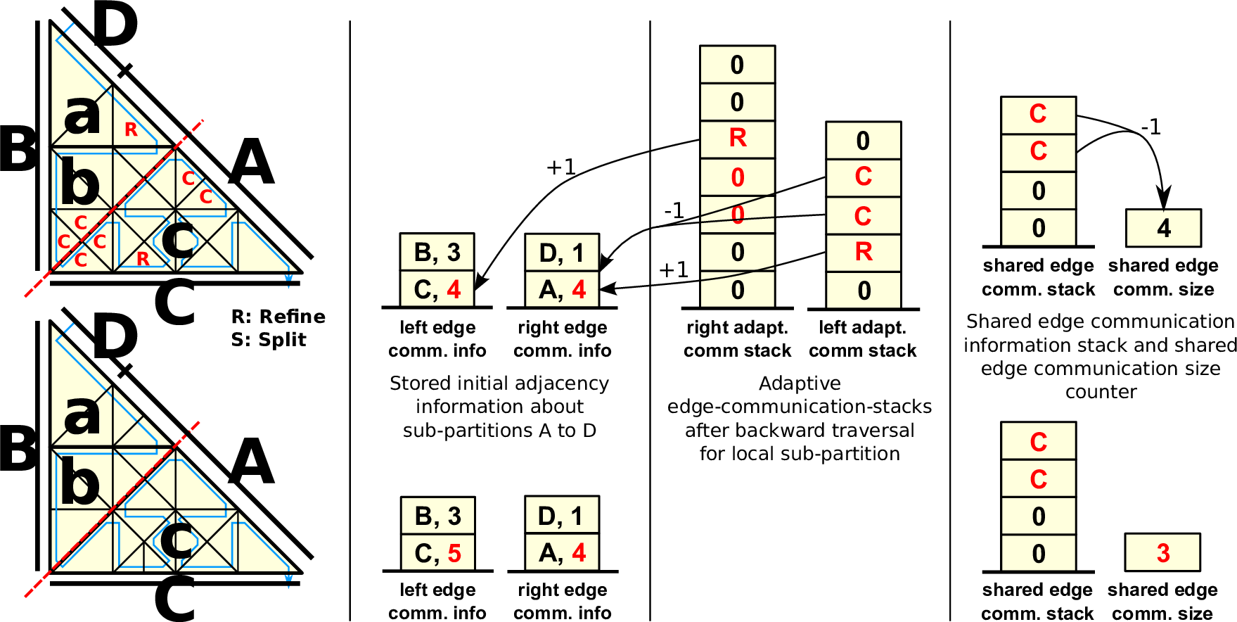
Instead of running only the last backward adaptivity traversal to refine and coarsen cells, we also transfer additional information on inserted and removed edges via the edge communication stacks. To generate data for the partition boundary dPi, we set the edge types of the partition boundaries to new and forward the following markers via edges:
After the grid traversal, the left and right edge communication stacks then store adaptivity markers on split (MR: inserting a vertex) and joined (2 × MC: removing a vertex) edges for the partition boundary dPi. This allows us to update the RLE meta information of the modified grid based on these markers only. An example is given in Fig. 5.7.
Updating the left and right RLE meta information is then accomplished by iterating over the respective adaptivity communication stack to which the adaptivity markers were written to. These markers describe the change in the RLE meta information due to the adaptivity step.
Algorithm: Updating communication meta information
Updating the vertex communication data is also transparent to this adaptivity process. By adding or removing edges via updating the RLE, this also accounts for updating the vertex-based communication information due to three properties:
Special care has to be taken for partitions consisting only of a single cell since a coarsening operation would lead to a partition only consisting of half a cell. These coarsening operations must be deactivated by invalidating the coarsening state on the adaptivity state stack.
The presented communication schemes are also applicable to partitions generated by SFC cuts.