Parallelization of simulations with (dynamic) adaptive mesh refinement has a rich history in scientific computing. SFC-based domain decomposition and load-balancing strategies are considered to be among the most efficient regarding our requirements of a changing grid in each time step (see related work in Section 3.4.1), and we continue with a more detailed introduction to SFC-based domain decomposition methods.
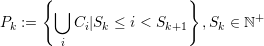
We start with an SFC-based domain decomposition of a discretized domain Ωd = ⋃ i{Ci} with cells Ci. By ordering and enumerating all cells along the SFC, a partitioning into N non-overlapping partitions Pk ∈ Ωd with 1 ≤ k ≤ N can be achieved: This associates cells to a partition k by generating an interval for each partition with the start cell id Sk and an end id given by the next partition’s cell start id Sk+1,
 between two different partitions Pi and Pj with i≠j
are given by a set of hyperfaces
between two different partitions Pi and Pj with i≠j
are given by a set of hyperfaces
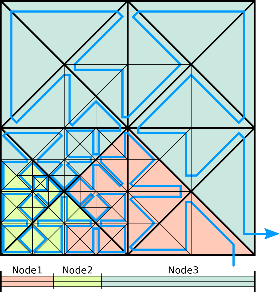
We further refer to hyperfaces created by the Sierpiński SFC to be edges (hyperfaces of dimension d - 1) and nodes (hyperfaces of dimension d - 2).
With the spacetree-based grid greneration inducing a serialization of the underlying grid cells with the SFC, there are two common ways on partitioning such a grid:
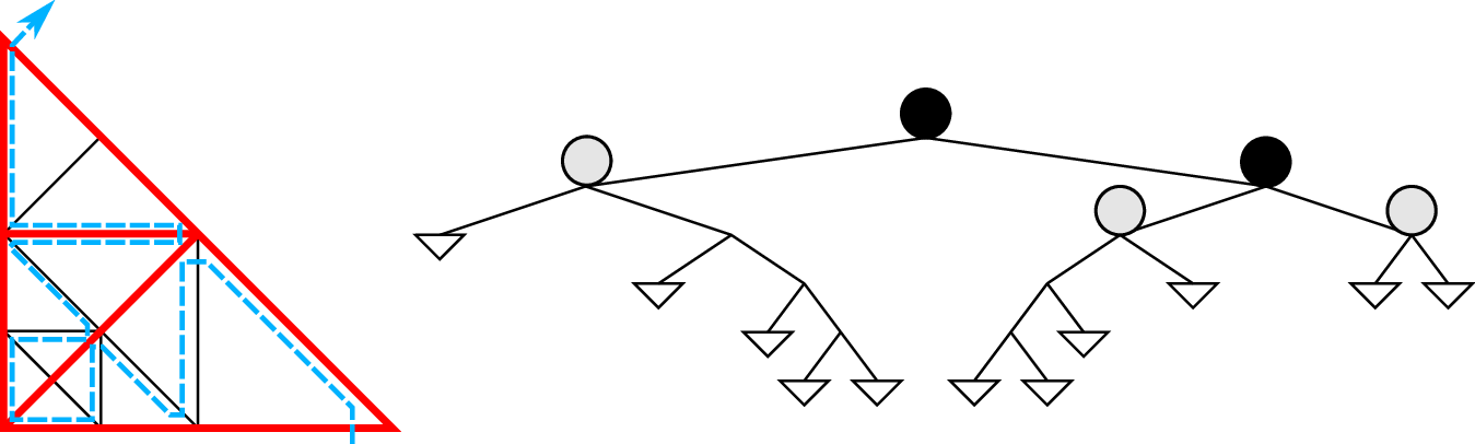
The communication, data migration and code-generator-based optimizations (see Sec. 4.10.1) which we derive in this thesis can be applied to spacetree splits and also SFC cuts. Due to historical reasons and the existing code generator for recursive traversals of subtrees, we decided to continue with the parallelization based on the tree splits.
We distinguish between parallelization approaches by considering methods with shared and replicated parallelization [SWB13b] 1 . Both methods are based on a domain decomposition into multiple partitions, each partition sharing hyperfaces of dimension d - 1 or less with adjacent partitions. We refer to these shared hyperfaces as shared interfaces dPk. With each compute unit executing operations and modifying data associated on each partition in parallel, data on these shared interfaces is accessed in parallel and has to be kept consistent. Based on our grid generated with a spacetree, we consider two different data access schemes, each one resulting in a different parallelization approach:
The replicated data scheme with separated data buffers (stacks and streams, e.g.) for each partition is typically used for distributed-memory environments since replicated data can be sent and reduced after the receive operation by using distributed-memory messaging. For shared-memory environments, such communication interfaces are typically not available or, lead to additional overhead. In this work, we developed a run-length encoding of meta information to make the replicated data scheme also feasible on shared-memory systems (see Section 5.2). Our method does not only avoid these overheads for shared-memory systems, but also leads to an elegant solution for distributed-memory parallelization. We continue to use the replicated-data scheme in the present work.
Once the partitions are generated, several scheduling possibilities exist to assign computations on SFC-based domain partitions to compute units.
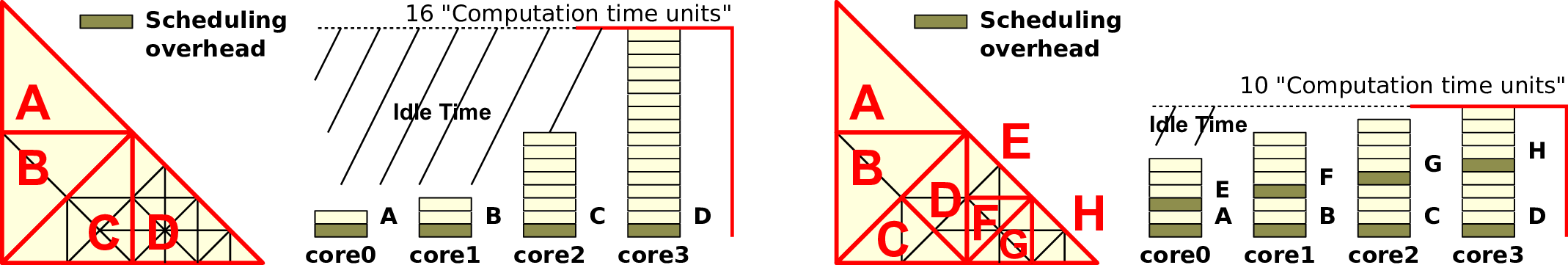
For SFC-cuts, a 1:1 partition scheduling allows an optimized implementation due to avoiding object-oriented overheads with single-threaded MPI (cf. [Vig12]). With the focus of our partition generation based on tree splits, such a 1:1 scheduling would lead to the above mentioned load imalances. Therefore, an N:1 scheduling as well as an object-oriented software approach gets mandatory to tackle the N:1 load balancing.